Hacking The Official WIFI B&D Garage Door Opener
This whole project is WIP. I am using this to dump things I find for documentation, as literally no one has tried to rev this before. If you make progress, PLEASE email me. I would love to hear it 😎.
(B&D / ATA, if you would like anything taken down, please email me, I will comply 😊)
Hub
Behind all the screws, there are 2 boards, the main hub board, and a daughterboard which carries the front button, LED, and radio module. It’s joined with a 6 pin cable.
UART is open on the main board, with a pre-soldered 4 pin header (strange 🤔). I dont have the male header, so I just soldered dupoints onto it. The pinout (from left to right) is:
G TX RX 3.3V
Baud Rate is 115200.
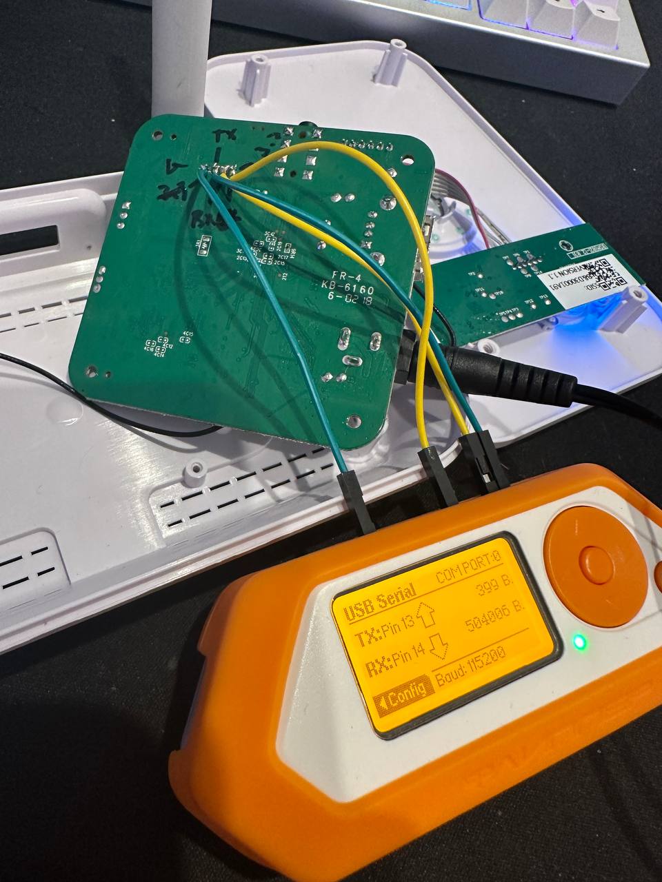 (shell with the flipper zero as UART to USB)
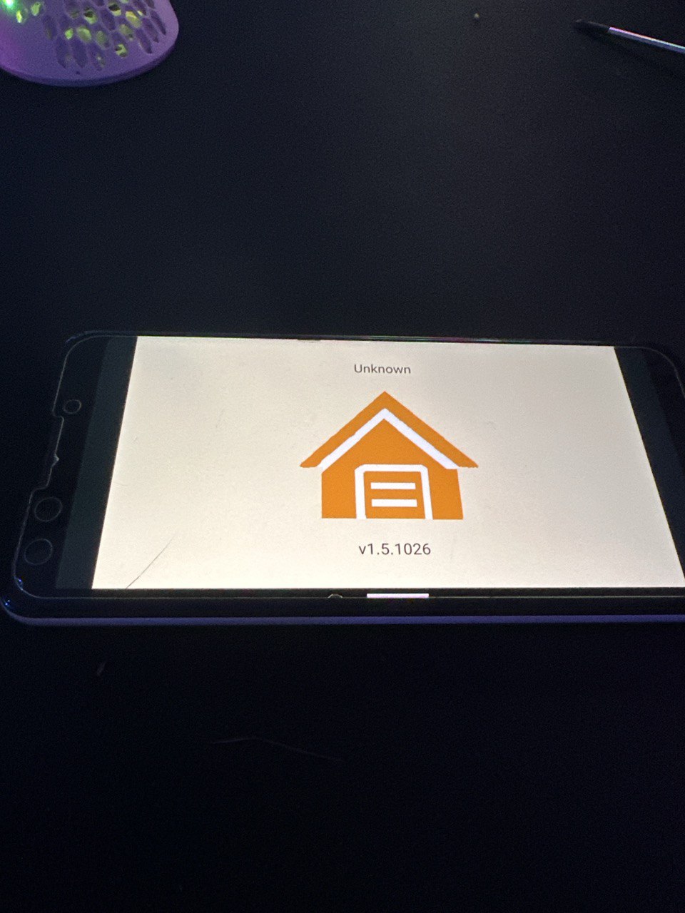
This gives us a root shell, we can see that the device is running android (strange 🤔)
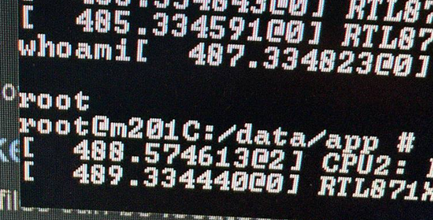
(terrible photo but you get the idea)
Theres 3 apps installed (along with standards like gservices)
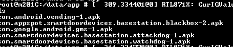
blackbox is the main app that does everything, here are dumps if you would like to have a little look 👀
The APK’s are obfuscated, jadx can decomp 99% of it
1
2
3
https://pixeldrain.com/u/vD3Xc9WA attackdog.apk
https://pixeldrain.com/u/doSd4bhu blackbox.apk
https://pixeldrain.com/u/cP6tDTJM watchdog.apk
Annoyingly, Frida refuses to run, probably because the android install has been debloated to the point its basically just embedded linux 😂

Note: blackbox will launch on a physical phone, but not do anything 😂
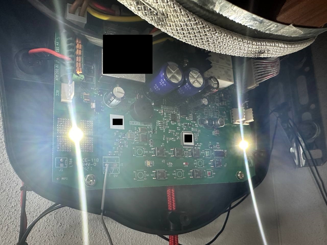
Door Roller (B&D Roll A Door)
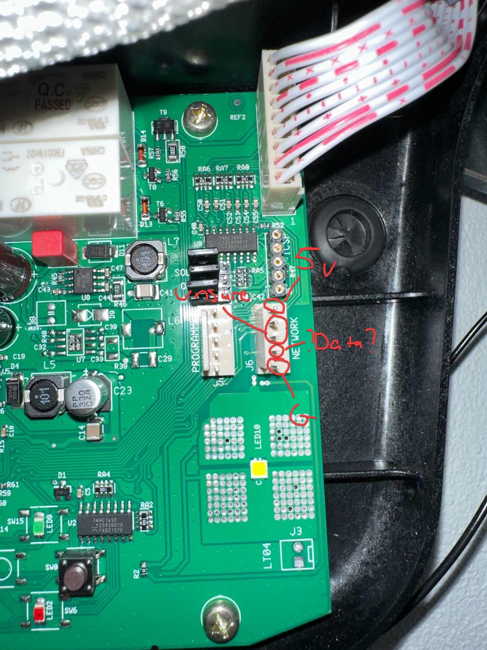
Not much to see here, pcb is pretty boring (removed serial numbers etc..):
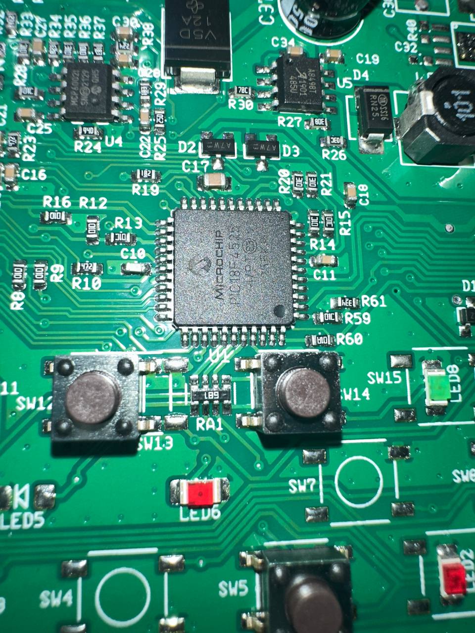
And the microcontroller its using (under a sticker):
RF Reciever
Whole idea of this product is for the hub to send a code to the reciever (NOT THE ROLLER), reciever processes it, and sends the corosponding code via ??serial?? to the door roller. The reciever plugs into the “network” port on the roller.
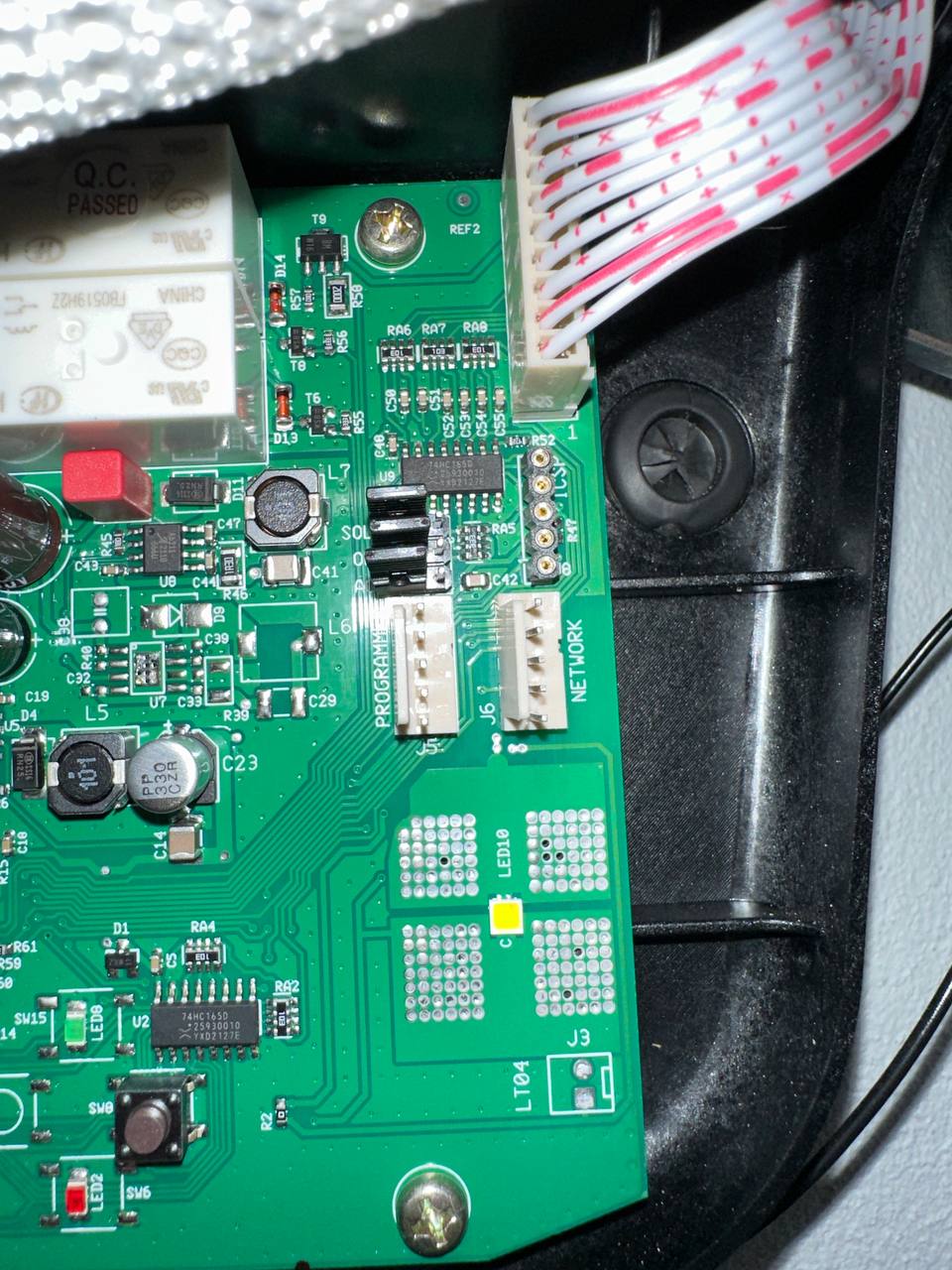
I have not really figured out the pinout, what I have is:
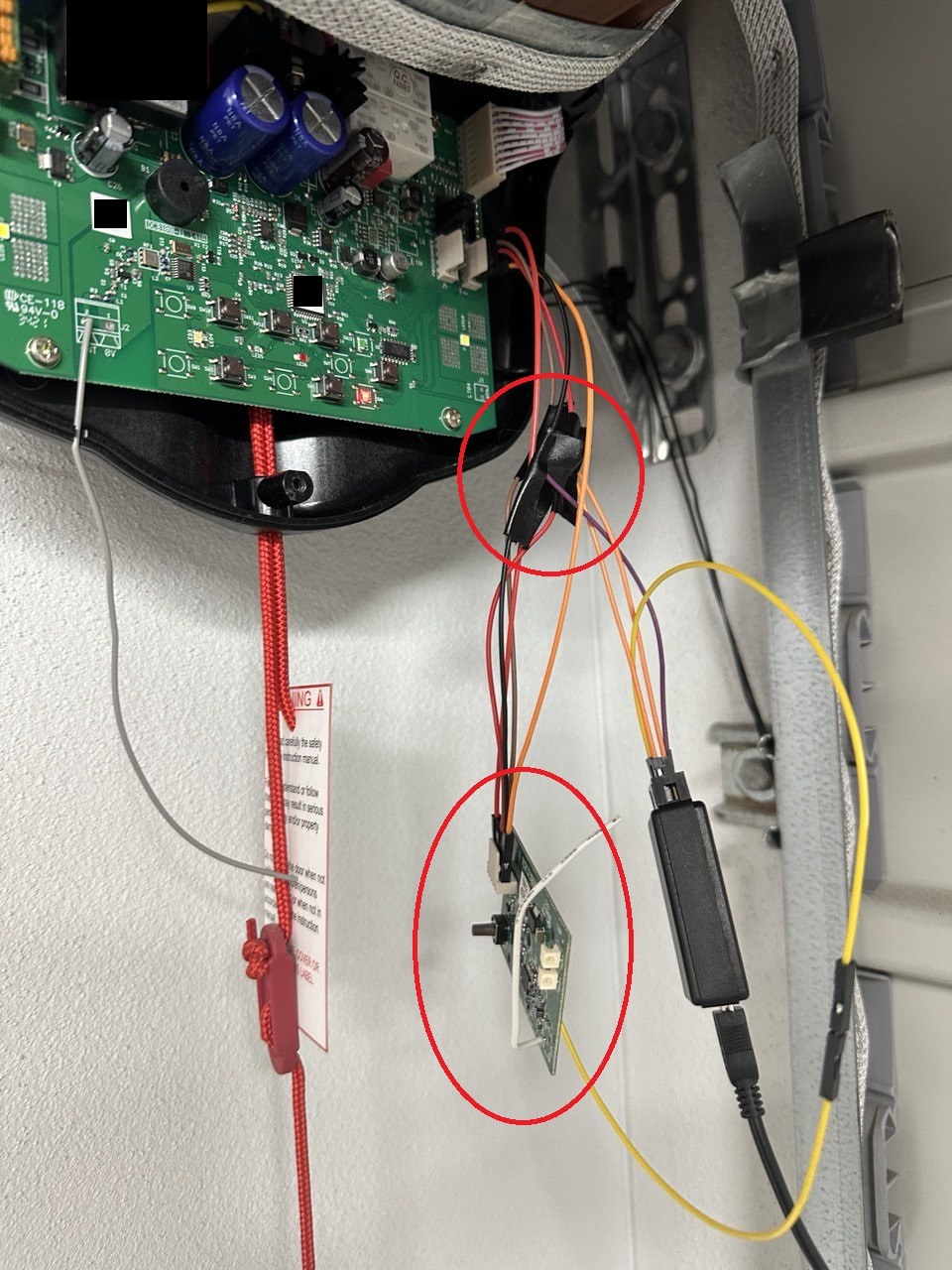
I attempted to view the data being transferred with a logic analyzer (never used one before 🤣). Soldered up a little jig.
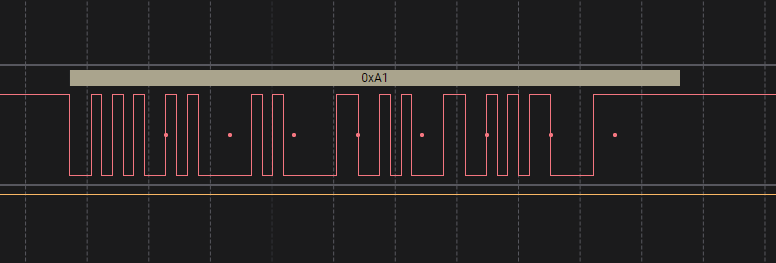
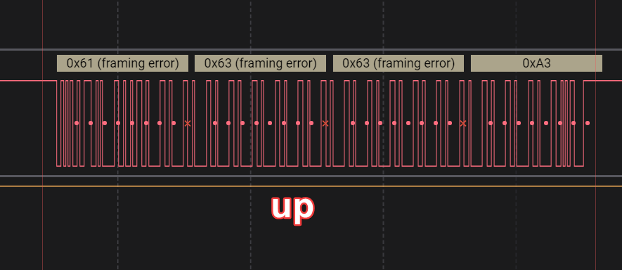
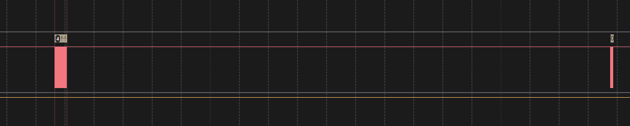
I can see when I send the up command through the app, this serial communication is transferred:
And down:
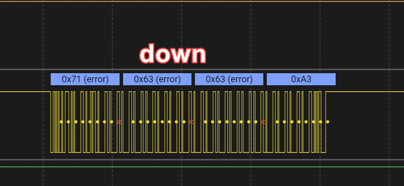
note: this probably isnt correct, but for now, we can see that its sending different signals for up & down. This was from the port labeled ??data?? on the photo above (door roller), 2nd from bottom.
There are also some ??sync bytes mabye?? everytime the position changes (up/down)
Whole signal looks like:
The other data: